| |
 |
Remote Monitoring Hardware and Software
Remote Monitoring and Power Quality Improvement Software
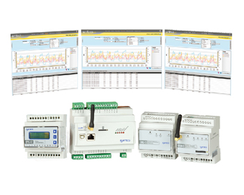
Entes remote monitoring solution transmits the electrical parameters measured on the system through the communication module, and then centralizes the monitoring and analysis of these values. The communication module can access and control thousands of devices through Ethernet and GPRS connections. Using Entbus Pro and Entbus Plus software, remote measurement results from different locations can be collected. Important data that need to be compared (such as power consumption, demand, reactive power ratio) can be analyzed by graphical display.
With this system, the application of monitoring power factor correction of power grid equipment, comparing power consumption at different locations and monitoring power consumption of machines on production lines become simpler, and the cost caused by faults can be avoided. With these systems, the measured results of instruments can be read from a single monitoring center on Entbus software. The DC parameters of remote locations that are difficult to reach (such as communication towers, solar farms and trains) can be transmitted to the monitoring center through remote monitoring hardware and software. |
| |
|
Remote monitoring software
●Entbus Pro
●Entbus@Plus
GPRS Modem RTU
●GEM-10/10SH
●GEM-15
Ethernet and USB Converter
●EMG series
●RS-USB2
●RPT-1
Pulse counter
●Main features of EPC-12 Entbus Pro
●Online monitoring
●Real-time data collection
●Alarm management
●Distance configuration of measuring equipment
●Report, graphical display and export of collected data
●Access via Internet/Intranet
●Multilingual support
●Adding different brands of Modbus-enabled equipment
●Define virtual devices or virtual parameters
●Detailed report screening function
●Alarm notification via SMS and/or e-mail |
Summary
The new generation of Entbus Pro network power monitoring software is your most important solution partner for power management. Entbus power management software with network structure has the advantages of reducing energy consumption, facility expenditure and helping you achieve the goal of reducing expenditure.
Entbus Pro power management software allows you to monitor the energy consumption of facilities in any corner of the world through the Internet. With Entbus network power monitoring software, you can use the communication function and connection points of the measuring equipment to record and archive long-term facility profiles through Ethernet/GPRS, such as gas, water, especially electricity.
Because Entbus uses a network interface, you can manage the power of facilities from anywhere in the world, such as comfortable homes or small offices.
With the help of hierarchical electricity information, you can optimize energy consumption for regional power management.
System Structure System Work
Data from communicable measurement devices are transmitted to the server via an Ethernet converter or a GPRS modem. Online users can access server data from anywhere.
●Monitoring screen:
It can monitor the electrical parameters of the equipment in real time and display the hierarchy of the equipment in the equipment tree.
●Options screen
Provide user information access and defined alarm parameters.
●Report screen
It consists of reports calculated from device data read instantly. There are 27 types of reports. Reports can be displayed as graphs and/or tables. Graphics can be exported in PNG and BMP formats, and tables can be saved in XLS, CSV and XHL formats.
Equipment commands
Device settings can be configured remotely. In addition, the device log with data recording function can also be displayed.
●Configuration
These are the basic configuration screens for Entbus. Area, connection point, equipment, user, alarm light definitions are executed in these menus. .
Alarm
When any parameter or power factor ratio of the device reaches the predefined value, the system notifies the corresponding user by short message and/or e-mail.
●Virtual Device
For unmeasurable points, the required values can be measured by defining virtual devices and virtual parameters.
All basic mathematical operations can be observed on the monitor screen, just like real devices. Therefore, loss and previously unmeasured consumption can be easily detected. |
| |
|
system architecture
There are two ways to use ENTBUSO Pro software.
Application Model 1: Install the software on your own server
In this application, users purchase software licenses, install software on their servers to collect data from intranets or networks, change the settings of their devices, analyze data, and create reports from them.
Therefore, the control of electric energy measurement equipment distributed in a wide area is simpler. With the network access function of this software, users can control their system anytime and anywhere.
Application Model 2: Using Software on www.entbus.com
In this simpler network application model, the software is installed on the Entes server. Users define their own devices to the Entes server, store their data on the Entes server, and change device settings, all without having to deal with any software installation or server purchase. In this way, users can connect to the Entes server through the network, access their data with their passwords, analyze the data and create reports.
Summary
Entbus@Plus V3.0 software reads and records data from field ENTES brand Modbus communication devices at user-defined intervals. The built-in reporting function uses these data. |
Structural characteristics
●The program consists of three modules. The server module collects data from field devices and records it to the database at the required time. MS SQL is used as a database.
●Monitoring module monitors parameters measured by field equipment. You can create a monitoring panel that contains a view of the front panel of the device, and create a personalized monitoring screen by creating a single line graph.
●The monitoring structure can be accessed by using web browser in the network module. It makes use of user-friendly, easily configurable and hierarchical structure to simplify the acquisition of needed analysis.
Functional characteristics
●The program only identifies Entes brand devices.
●Two user levels can be defined. Administrator level allows users to access all aspects of the program. The remote device configuration, schematic design and program settings section of the operator-level restricted user access program.
●The data of field equipment can be monitored on a schematic screen or table displaying all equipment parameters.
●After user authorization, configurable parameters of field equipment can be changed.
●Simulated drawings can be designed.
●Hourly, daily or monthly power reports can be created.
●Maximum reports per hour, day or month can be created.
●Periodic value reports can be obtained at storage intervals. The minimum storage interval is 1 minute.
●Total power report, reactive power compensation and regional power report can be created. |
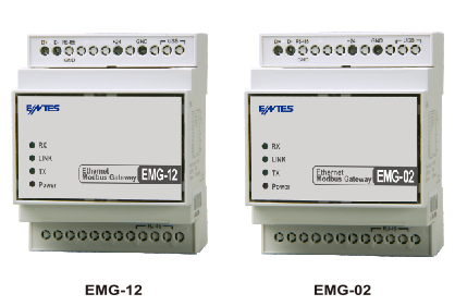 |
Communication Converter EMG/RS-USB Series
EMG-021 EMG-12
RS-4851 Ethernet Modem
The Ethernet / RS-485 Modbus gateway is used to communicate PC with MPR / EPR and EPM series through the Internet (WAN) and Intranet (LAN). |
|
category |
Explain |
|
Network protocol |
TCP/IP ARP, ICMP, HTTP Modbus TCP |
|
Serial port |
Rs485 and USB Configuration |
|
Working mode |
ModbusTCP/RTU And Tunelling |
|
Network Interface |
10/100 Mbps Self coordination |
|
baud rate |
1200-115200 bps |
|
Power Supply |
9-24V AC- 9-30V DC or (~100 mA), USB port |
|
Isolation and protection |
Rs485 port: 500V
Ethernet Port: 1500V
15KV ESD Protect USB Port
10/1000 us (600W) instantaneous pulse
ProteRS-485 Port |
|
Shell type |
DIN4 (Track installation) |
|
USB Converter (RS-USB2)
RS-485/USB converter is used for PC to communicate with MPR/EPR and EPM-0x series.
RPT-1
RS-485 to RS-485 transponders
●Variable baud rate
300,... 9600,... 115K
●Variable data format |
technical specifications
●USB1.1 and USB2.0 support
●300-115.200 BPS baud rate
●Automatic Directional Flow Control on RS485
●Minimum 3000VDC Isolation Protection
●start LED
●Get power from USB port without external power supply.
●Automatic Baud Rate Detection
●ESD (Electrostatic Discharge) Protection |
|
Product Selection Table |
|
Maximum number of devices available for Connect |
1 Online connection |
4 Online connection |
Pieces / boxes |
Power Supply |
|
Product code |
|
RS-USB2 |
RS 485/USBConverter |
32 |
|
|
1 |
|
|
EMG-02 |
Ethernet-Modbus Gateway |
2 |
|
● |
1 |
・ |
|
EMG-12 |
Ethernet-Modbus Gateway |
32 |
|
● |
1 |
・ |
|
RPT-1 |
RS 485 to RS-485 transponders |
32 |
|
|
1 |
・ |
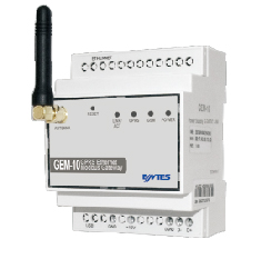 |
GPRS OEM Modem
GEM-1O/ 10SH
Summary
GEM-10 GPRS/Modbus Gateway allows Connect to Signal Communication devices over GPRS or Ethernet network via Modbus protocol. With GEM-10, you can use GPRS or Ethernet and Modbus TCP Signal communication, or can use these Connect options as alternatives to each other.
GEM-10SH can use its Serial Port to read instruments that support the IEC 62056-61 Object Recognition System (OBIS) protocol.
Design of remote instrument reading system. The development of GEM-10SH establishes a system for reading and comparing instruments from various centers through Entbus electric energy monitoring soft piece. |
|
category |
Explain |
|
Network protocol |
TCP/IP ARP, ICMP, HTTP Modbus TCP |
|
Serial port |
Rs485 and USB for Signal Communication
USB port for configuration |
|
Working mode |
ModbusTCP/RTU和ModbusTune |
|
Network Interface |
10/100 Mbps self-coordination |
|
baud rate |
1200-115200 bps |
|
Power Supply |
12-20V DC |
|
Isolation and protection |
Rs485 port: 500V
Ethernet Port: 1500V
15KV ESD Protect USB Port
10/1000 us (600W) instantaneous pulse
ProteRS-485 Port |
Specifications
|
|
GEM-10 |
GEM-10SH |
|
Shell |
|
size |
90x7 1x80 mm |
|
Protection level |
Ip40front panel,IP54 Optional |
|
weight |
0.4kg/equipment; 12 pieces/ Packing |
|
Signal communication |
|
Signal communication Agreement |
MODBUS TCP/RTU adopt TCP |
|
Ethernet |
IEEE 802-3, 802-2 |
|
Isolation voltage |
1.5kV |
|
GPRS |
|
|
Four-band downlink |
850/900/1 800/1900 MHz |
|
Link speed |
Max 85.6 kbps |
|
Uplink speed |
Max 21.4 kbps |
|
Online Connect |
1 |
|
Number of Max devices that can be built and connected |
32 |
|
port |
Modbus (RS-485), USB (Mini), Ethernet(RJ45) |
|
Configure Interface |
MiniUSB Port, Ethernet (Network Interface Configuration) |
|
standard |
|
Power metering |
|
IEC 62056-61 OBIS Agreement |
|
Power Supply |
|
working voltage |
190-260V AC |
|
input Voltage |
12-20V DC |
|
Power waste |
<5 W |
|
working frequency |
50/60Hz |
|
environment condition |
|
ambient temperature |
-20/ +60℃ |
|
Storage temperature |
-30/ +70℃ |
|
humidity |
10%-85% |
|
Isolation and protection |
USB Port 15kV ESD Ethernet 500V
Modbus/RS485 500V Isolation and Short Circuit
GPRS Mobile Base Station Class B
Instantaneous pulse 10/1000us (600W) |
|
Connect |
|
install |
DINTrack installation |
|
Connection terminal |
With screws |
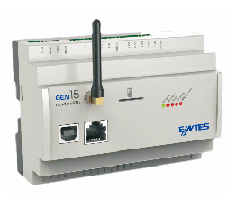 |
Modem RTU
GEM-15
Summary
GEM-15 modem RTU is a modem with advanced I/O function. It can use GPRS or Ethernet facilities as alternatives to each other. GEM-15 can detect the values to be monitored remotely (such as temperature, humidity, pressure, electrical parameters, etc.) through analog or digital output, and perform control operations through analog, digital and repeater output.
With the Modbus RTU protocol, which supports serial communication, it can communicate with all other devices in this facility, read information from its registers, specify alarms on devices, and establish control mechanisms that depend on these devices.
GEM-15 can be configured remotely with its own software to monitor the analog and digital input of the connected devices and obtain reports to create analysis. Inserting SIM card can provide users with real-time alarm monitoring through short message on mobile phone. |
|
|
GEM-15 |
|
Summary |
|
|
Power Supply |
9-36V DC, protect |
|
power |
< 5W |
|
CPU Clock frequency |
80 MHZ |
|
RTC(Real time clock) |
可用 |
|
input Wave filter |
Wave filters with median and average values are applied to simulated input. Digital input contains an analog low-pass Wave filter. There is one or two soft piece anti-jitter control Wave filters. |
|
Digital I/Of requency |
Digital output: OFF to ON response 32us, ON to OFF response 150us
Digital input: OFF to ON response < 2ms, ON to OFF response < 12ms |
|
ADC sampling time |
Samples were collected for each channel at 640 SPS (number of samples per second).
Speed after filtering operation: 4 SPS |
|
Program loading |
Updating Fixed Piece and Applications via USB |
|
Signal communication |
|
|
GSM |
GPRS, MODBUS TCP support |
|
Serial port(RS485) |
15 kV ESD protect ,Electrical insulation,MODBUS RTU |
|
environment condition |
|
|
working temperature |
-20/ +50℃ |
|
Storage temperature |
-40/ +85℃ |
|
humidity |
95% |
|
Working height |
<2000m |
|
Integrated input output |
|
|
Digital input |
4 (Sink) |
|
Voltage Range |
0-50VDC |
|
ON level |
5VDC-50VDC |
|
input Electric current |
0-3VDC |
|
Max input Electric current |
type 0.70 mA 24 VDC |
|
Max input Electric current |
1.50 mA 50 VDC |
|
Input impedance |
>3.3 MΩ |
|
Input GND Common Lead |
1 (4Point / public)insulation |
|
Maks. Tow Electric current (24VDC) |
Max 5.6mA (All inputOn) |
|
Maks. Tow Electric current (50VDC) |
Max 12.04mA (All inputOn) |
|
OFF to ON response |
< 2ms |
|
ON到OFF响应 |
< 12ms |
|
insulation |
1kV |
|
Digital output |
|
|
Modular output |
4 (Sink)Output band transistor |
|
Voltage Range |
3,3-50VDC |
|
Max output Electric current |
125 mA/Point,500 mA/public |
|
Min output Electric current |
0.42 mA/点,1.68 mA/公共(3.3 V) |
|
Max leakage current |
0.01 mA I |
|
voltage drop |
2.3 VDC @0.76 mA |
|
OFF response to IN |
32 μs |
|
ON response to OFF |
150 μs |
|
nput GND leads the public |
1 (4 / public) isolation |
|
external Voltage input |
5- 50 VDCMax 48 mA (All outputOn) |
|
Max Tow Electric current |
Max 0.5A (All outputOn) |
|
Simulated input |
|
|
Electric current input cabinet |
2 |
|
Modular Voltage input |
2 |
|
Electric current input accuracy |
1% accuracy ,12 place Resolving power |
|
Electric current input |
1% accuracy ,12 place Resolving power |
|
Voltage input |
0(4)-20mA |
|
|
120 Ω |
|
Voltage input |
0(2)-10V |
|
|
40 kΩ |
|
Repeater output |
1 (4 points / public) |
|
Modular output |
|
|
Modular output |
4 repeater |
|
Max Contact Electric current |
Com-No (Usually open)3A@250VAC |
|
Journal |
|
|
Logging Time Resolution |
1s |
|
Logging capacity |
Store 19600 parameters, time stamp and parameter information |
|
alarm system Log record |
Storage parameters and start and end time timestamps |
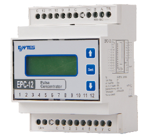 |
Pulse concentrator
EPC-12
routine
●Collection of pulses from power, water and gas meters
●12 different instrumentation inputs
●Define 8 different rates for each instrument, such as workdays, Saturdays, Sundays and holidays
●DST (Summer Time) Function
●RS-485 Communication
Configuration software
Using configuration software, all equipment parameters can be changed and all consumption values (electricity, water or gas) can be monitored on the computer screen.
●All equipment parameters can be changed
●Real-time value pages
●Total consumption calculated at rates
●Access Logging |
Specifications
|
|
EPC-12 |
|
Shell |
|
|
size |
DIN 4 (PK27) |
|
Protection level |
IP40 |
|
weight |
456.4g |
|
display |
Backlight 2x12 LCD |
|
PALS |
|
|
Min pulse width |
10ms |
|
Min pulse interval |
30ms |
|
Min pulse cycle |
60ms |
|
Min pulse frequency |
16Hz |
|
Min pulse impedance |
800 ohm |
|
pulse Voltage |
10 V |
|
Trigger edge |
The rise and pulse width control |
|
Total counter capacity |
34359738368 |
|
Power Supply |
|
|
working voltage |
190-260V AC |
|
Power waste |
<5VA |
|
working frequency |
45-65 Hz |
|
standard |
|
|
safety standards |
EN 61010-1 |
|
Terminal Protection Level |
IP 00 |
|
environment condition |
|
|
ambient temperature |
-25/ +55℃ |
|
Storage temperature |
25/ +70℃ |
|
humidity |
95% |
|
Connect |
|
|
install |
Track installation |
|
line type |
Terminal track |
|
Voltage Connecting line thickness |
2.5mm2 |
|
pulse Adding wiring thickness |
1.5mm2 |
|
RS-485 Connecting line thickness |
5 kinds of cables |
|
communication interface 协议 |
MODBUS RTU (RS-485) |
|
Parity |
No, odd, even |
|
address |
1-247 |
|
transmission speed |
2400-38400 bps |
|
Maximum communication distance |
1200m | |
|
|
|
| |
|
|
|